PIC 12F675 Equipment Test Cycle
Controller with Variable Duty Cycle
by Aaron Garber
 Background:
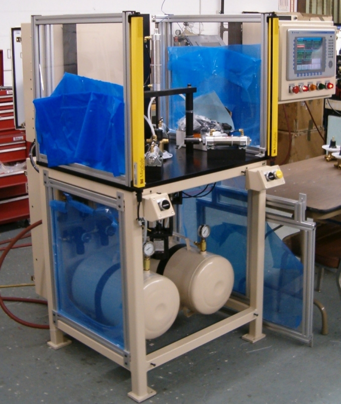
At my day job, we build custom test equipment and fixturing. (See attached
picture for a typical machine.) For troubleshooting purposes, I often need
to set up the equipment to automatically cycle for an extended period of
time. In the past, I would either modify the existing PLC program or borrow
an PLC from an upcoming project. The downside was that I might forget to
restore the program to its original state (possible safety issue) or we
wouldn’t have an extra (expensive) PLC lying around to borrow. Plus,
I always had to drag the laptop out to the shop floor and knock together
a quick little program to make everything happen. I got tired of doing this,
so one Saturday I built this little project with about $5 worth of components.
Circuit Description:
1. Power from the machine, typically 24 vdc, is supplied to J2-1 and J2-2,
which feeds a 7805 voltage regulator to supply the PIC.
2. Reset button on MCLR allows user to reset the PIC and start the timing
sequence from zero.
3. ALIVE led flashes every 0.5 seconds just to let the user know the thing
is executing its program.
4. An optoisolator (from my junkbox) is driven by GP2.
5. The optoisolator drives a relay robbed from a dead PLC.
Link
to picture of the PCL
Link
to product information
6. The relay’s coil voltage is 4.5vdc. Setting JP1 allows the relay
to use power either from the 7805 regulator or from the machine. R4 and R5
need to be sized based on the supply voltage and rated coil voltage.
7. Relay contacts (J1-1 and J1-2) are wired in parallel with the machine’s
start button.
8. Potentiometer allows the user to manually set the amount of time between
subsequent machine cycles.
Software Description:
A PIC12F675 reads the voltage from the potentiometer wiper connected to AN0.
Timer0 rolls over on a 0.5 second interval and toggles ALIVE led to let the
user know the program is running. A register is also incremented for each
timer rollover. When the number of timer0 roll-overs is greater than or equal
to the A/D counts, the relay will turn on for 0.5 seconds to initiate a machine
cycle. Thus, by setting the pot, the delay between machine cycles can be
adjusted from approximately 0 to 8.5 minutes. The contacts of the relay are
wired in parallel with the machine’s start button(s).
Let me know if I forgot to include anything or you need any clarifications.
Regards,
Aaron Garber
;**********************************************************************
;                                                                     *
;    Filename:      Pulser.asm                                        *
;    Date:          2-25-05                                           *
;    File Version:                                                    *
;                                                                     *
;    Author:        Aaron Garber                                      *
;                                                                     *
;**********************************************************************
;                                                                     *
;    Files required:                                                  *
;                   12F675i.lkr                                       *
;                   P12F675.inc                                       *
;                                                                     *
;**********************************************************************
;                                                                     *
;    Notes:                                                           *
;           A quick and dirty program.  Reads pot connected to AN0.   *
;           A TMR1 interrupt occurs every 0.5 seconds.                *
;           When the number of TMR1 rollovers >= the A/D result, a    *
;           relay will be turned on for a 0.5 second pulse.           *
;                                                                     *
;**********************************************************************

	list      p=12f675          ; list directive to define processor
	#include <p12f675.inc>      ; processor specific variable definitions

    radix   dec

	errorlevel  -302            ; suppress message 302 from list file

	__CONFIG   _CP_OFF & _CPD_OFF & _BODEN_OFF & _MCLRE_ON & _WDT_OFF & _PWRTE_ON & _INTRC_OSC_CLKOUT

; pin definitions
;       GP0 - Analog input from wiper of 5k pot.  Sets delay time between 0.5 second relay pulses.
;       GP1 - Not used.
;       GP2 - Drives 4N32 optoisolator thru 200 ohm resistor.  4N32 then drives relay output.  Delays between 0.5 second relay pulses are set by pot.
;       GP3 - Reset button between ground and MCLR.  MCLR tied high via 10k resister.
;       GP4 - Fosc/4 clockout for debug purposes.
;       GP5 - Drives an LED on a clock tick.  Visual indication that program is working.


; #defines
    #define pot         GPIO, GP0
    #define relay       GPIO, GP2
    #define aliveLED    GPIO, GP5

; Shared Uninitialized Data Section
INT_VAR     UDATA_SHR   0x20
w_temp      RES     1       ; variable used for context saving
status_temp	RES     1       ; variable used for context saving

rollcntL    RES     1       ; low byte of TMR1 rollovers
rollcntH    RES     1       ; high byte of TMR1 rollovers

rollflag    RES     1       ; bit 0 = TMR1 rollover flag for main loop to poll


;**********************************************************************
RESET_VECTOR    CODE    0x000   ; processor reset vector
		goto    main            ; go to beginning of program

INT_VECTOR      CODE    0x004   ; interrupt vector location
		movwf   w_temp          ; save off current W register contents
		movf    STATUS,w        ; move status register into W register
		movwf   status_temp     ; save off contents of STATUS register

 ; check for TMR1 rollover
        banksel PIR1
        btfss   PIR1, TMR1IF    ; TMR1 rollover?
        goto    nextIRQ
        movlw   0xBD            ; reload TMR1
        banksel TMR1L
        movwf   TMR1L
        movlw   0xB
        banksel TMR1H
        movwf   TMR1H

        banksel GPIO
        bcf     relay           ; turn off relay

        banksel GPIO
        movlw   b'00100000'     ; toggle aliveLED for visual indication
        xorwf   GPIO, f

        banksel rollflag
        bsf     rollflag, 0     ; set roll-over flag for main loop to poll

        banksel PIR1
        bcf     PIR1, TMR1IF    ; clear interrupt flag

nextIRQ
		movf    status_temp,w   ; retrieve copy of STATUS register
		movwf	STATUS          ; restore pre-isr STATUS register contents
		swapf   w_temp,f
		swapf   w_temp,w        ; restore pre-isr W register contents
		retfie                  ; return from interrupt


; Main Code
main
		call    0x3FF           ; retrieve factory calibration value
		banksel OSCCAL
		movwf   OSCCAL          ; update register with factory cal value

; initialize variables
        banksel rollcntL
        clrf    rollcntL
        banksel rollcntH
        clrf    rollcntH
        banksel rollflag
        clrf    rollflag

; set up direction of I/O pins
        banksel TRISIO
        movlw   b'00000001'
        ;         xx------  not implemented
        ;         --0-----  0=output, GP5, Drives an LED on a clock tick.  Visual indication that program is working.
        ;         ---0----  0=output, GP4, Fosc/4 clockout for debug purposes
        ;         ----x---  not used, GP3, Dedicated to MCLR
        ;         -----0--  0=output, GP2, Optoisolator, relay driver
        ;         ------0-  0=output, GP1, not used (output defective)
        ;         -------1  1=input, GP0, analog input
        movwf   TRISIO

; set up comparator
        banksel CMCON
        movlw   b'00000111'
        ;         x-------  not implemented
        ;         -0------  output bit
        ;         --x-----  not implemented
        ;         ---0----  0=non-inverted output
        ;         ----0---  0=Vin- to Cin-
        ;         -----111  111=comparator off
        movwf   CMCON

; set up A/D converter
        banksel ANSEL
        movlw   b'00010001'
        ;         x-------  not implemented
        ;         -001----  001=Focs/8 Conversion Clock
        ;         ----0---  0=digital I/O, GP4, Fosc/4 clockout for debug purposes.
        ;         -----0--  0=digital I/O, GP2, Optoisolator, relay driver
        ;         ------0-  0=digital I/O, GP1, not used
        ;         -------1  1=analog  I/O, GP0, analog input
        movwf   ANSEL

        banksel ADCON0
        movlw   b'10000001'
        ;         1-------  1=right justified result
        ;         -0------  0=Vdd is voltage reference
        ;         --xx----  not implemented
        ;         ----00--  00=select channel 0 (GP0)
        ;         ------0-  0=A/D conversion not started
        ;         -------1  1=A/D converter module is operating
        movwf   ADCON0

; initialize output pins
init
        banksel GPIO
        movlw   b'00000000'
        movwf   GPIO

; initialize interrupts
        banksel INTCON
        movlw   b'01000000'
        ;         0-------  0=interrupts disabled
        ;         -1------  1=enable peripheral interrupts
        ;         --0-----  0=disable TMR0 overflow interrupt
        ;         ---0----  0=disable GP2/INT external interrupt
        ;         ----0---  0=disable GPIO port change interrupt
        ;         -----0--  0=no on TMR0 overflow
        ;         ------0-  0=no GP2/INT external interrupt
        ;         -------0  0=no GPIO port change
        movwf   INTCON

        banksel PIE1
        movlw   b'00000001'
        ;         0-------  0=disable EE write complete interrupt
        ;         -0------  0=disable A/D converter interrupt
        ;         --xx----  not implemented
        ;         ----0---  0=comparator interrupt disabled
        ;         -----xx-  not implemented
        ;         -------1  1=enable TMR1 overflow interrupt
        movwf   PIE1

        banksel PIR1
        movlw   b'00000000'
        ;         0------- 0=no EE write complete
        ;         -0------ 0=no A/D conversion complete
        ;         --xx---- not implemented
        ;         ----0--- 0=no comparator interrupt
        ;         -----xx- not implemented
        ;         -------0 0=no TMR1 overflow
        movwf   PIR1

; initialize TMR1
        banksel T1CON
        movlw  b'00110101'
        ;       x-------  not implemented
        ;       -0------  0=gate disabled
        ;       --11----  01=1:8 prescaler
        ;       ----0---  0=LP oscillator is off
        ;       -----1--  1=external clock input not synchronized
        ;       ------0-  0=internal clock
        ;       -------1  1=enable timer
        movwf   T1CON

    ; preload for 500ms rollover @ 4 MHZ internal oscillator
    ; Fosc/4 = 1 MHZ = 1 uS per clock
    ; 500000 clocks per 500 ms
    ; with 1:8 prescaler: 65535 - (500000/8) = 3035 = 0xBDB initial value
        banksel TMR1L
        movlw   0xDB
        movwf   TMR1L
        banksel TMR1H
        movlw   0xB
        movwf   TMR1H

        banksel INTCON
        bsf     INTCON, GIE     ; enable interrupts

; Main Loop
forever
        banksel ADCON0
        bsf     ADCON0, GO      ; start A/D conversion
        btfsc   ADCON0, NOT_DONE
        goto    $-1

        banksel rollflag
        btfsc   rollflag, 0     ; TMR1 rollover?
        call    compare

        goto    forever

; Compare subroutine - Test rollover counter to see if it >= the A/D result.
; If it is we turn on the relay.
compare
        banksel rollflag
        bcf     rollflag, 0     ; reset ISR rollover flag

    ; increment number of rollovers
        banksel rollcntL
        incf    rollcntL, f     ; number of rollovers
        btfsc   STATUS, Z       ; more than 255 rollovers?
        incf    rollcntH, f     ; yes, increment high byte of rollover counter

    ; compare to see if rollover counter is >= A/D result (16 bit unsigned comparision)
        banksel ADRESH
        movfw   ADRESH
        banksel rollcntH
        subwf   rollcntH, w     ; w = rollcntH - ADRESH
        btfss   STATUS, C       ; if rollcntH >= ADRESH, C=1
        return
        btfss   STATUS, Z       ; if rollcntH = ADRESH, C=1
        goto    relay_on
        banksel ADRESL
        movfw   ADRESL
        banksel rollcntL
        subwf   rollcntL, w     ; w = rollcntL - ADRESL
        btfss   STATUS, C       ; if rollcntL >= ADRESL, C=1
        return

    ; rollover counter >= A/D result
relay_on
        banksel rollcntL        ; reset roll-over counters
        clrf    rollcntL
        banksel rollcntH
        clrf    rollcntH

        banksel GPIO            ; turn on relay
        bsf     relay
        return


; initialize eeprom locations
EE		CODE	0x2100
		DE	0x00, 0x01, 0x02, 0x03


		END