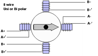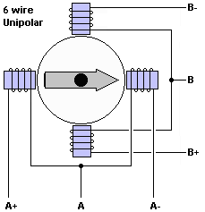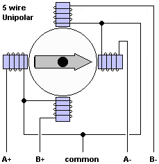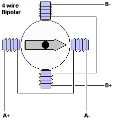

These days, most of the time, it's Red, Blue, Green, Black, in that order. Red and Blue are the first coil, Green and Black are the second, and if you wire them to the driver in that order, it will "just work".
Note, however, that if you are using the Pololu standard connections, they have the phases ordered: 1B, 1A, 2A, 2B. So for that connection, you want the wires to be Blue, Red, Green, Black.
Also: Stepper Motor Connection Options All the different ways you can hook your motor up, once you know which wire is what. Compares Unipolar, Bipolar Serial, Bipolar Parallel, Bipolar Single
NEW! Roman Black's Linistepper controller kit
Motor wiring diagrams (for reference)

 |

 |
Phil Ritchey says:
[When I] hooked up the motor in SERIAL Bi-POLAR configuration I discovered: Once wired into two each 2 coils sets, shorting the ends of either of those sets together LOCKS the motor. But if you get the ends of a coil identified wrong (Backwards), the coil will NOT LOCK. A further test that you got it correct.
Questions:
I am trying to ADD a 2d bipolar (identical) step motor to each of two already working CNC X and Y axis. Motor are NEMA23 and coils are 2.8 Ohm, 12v. The new motors will also point out, but on the opposite sides of the machine which requires that they turn opposite of the current pair. To make this difficult, they will also be connected to the current drivers for the X and Y. My question... do I simply wire the new motors directly to the current connecter (but flip the plug on them, or due to the low 2.8Ohm/phase wire them in series (but backwards) ?
James Newton of MassMind replies: I would add another stepper motor driver, run from the same step and direction signals, and wire the motor to the driver so it runs backwards.+
From Bill Kruise Says, great info, I have the wires ID'ed 1-8, My question is how to apply the #'s to the drawing above, 1-8 as you go around the drawing?
James Newton of Massmind replies: 1,2,3,4 are A+, A+', A-', A-. 5,6,7,8 are B+, B+', B-', B-.+
I have a rather backward question... I want to control a stepper motor without a controller or PC.
I want to wire two stepper motors together so one is hand cranked, an alternator, that drives the second stepper motor...
I just can't find a diagram explaining how to do this.
Any advice would be greatly appreciated.
James.
Hello; i have a stepper motor by superior electric, slo-syn, sunchronous/stepping motor. type m061-fd-6002e. 5vdc. It has 8 wires. I cannot find the product sheet. I even tried contacting superior electric, but with no reply. i can find the pairs easy enough, but cannot figure out the correct way to connect up the wires to an arduino board. Any help at this point would be really appreciated. I'm tearing my hair out, and i havnt got much left!!
James Newton of Massmind replies: Instructions for figuring out the wiring of an 8 wire motor are just above on this page.+
I want to use stepper motor to charge my 15 plates 12 Volts battery. How many stepper motors should I use for a possible parallel connection? What would be an appropriate way to make parallel connections to obtain suitable voltage and current?
James Newton of James Newton's Massmind replies: Your question is apparently related to using a stepper motor as a generator, which I do not yet have any information about.+
I have an older animatics 4 axis unipolar stepper controller and I would like to connect an 8 wire 2 phase Vexta stepper motor to it. The controller has output leads numbered 1-8 with no markings of A,-A,B,-B. Is there any way of testing the driver output leads to know which 8 leads of the motor (A,-A, A,-A, B,-B, B,-B) to connect to the driver leads 1-8?
James Newton replies: The only idea that comes to mind is to fire up the controller with a set of resistors connected from each output to ground. Then measure what the outputs do after each step pulse is applied. What resistor value to use? I have no idea.+
hello:
i bought a steper motor from farnell comp they didn't give us data sheet for the steppr ,the stepper has 6 leads ,driver also comes with the stepper i need to knw how can connect these pins to the driver,the driver take only 4 leads but what bout the other two,are they gruonded or what?plz help me
James Newton replies: Notice from the pictures at the top of this page that a 6 wire unipolar motor looks just like a 4 wire bipolar motor if you simply ignore (do not connect) the "common" leads (A and B in the pictures) and instead connect only A-, A+, B-, and B+. Figuring out which lead is which is what the rest of the page is all about.+
I have 4 axis Micro Step Motor drive with coil markings A,-A,B,-B. The 8 wire Stepper Motor has markings for Bi-Polar A,-A,-C,
C,B,-B,-D,D. How do I connect the 8 motor wires to the 4 post of the Driver Board ??
http://www.qsl.net/pe1rok It seems to me that the coils are labelled correctly, but placed wrong. A1 and A2 are each other's opposite instead of neighbors. On the 'steppers.htm' page it is right. On this page (wires.htm) it is not drawn right.
The recipe to identify the wires is helpful. I may add that identifying wires with six (or 5-wire) motors the ohmmeter method is the easiest. Who really cares about the sequence. If it is not right, swap a1 and a2, or b1 and b2.
James Newton replies: Yes, they were wrong, thank you for pointing that out. I've corrected them now, please let me know if these are again correct. +
If it really has three coils, I would guess it needs a special driver that produces 3 phases rather than the more common 4.
~NOSPAM~proto_n@spam@ at ~NOSPAM~yahoo.com responds:
To James Newton: My stepper (an old one, from Robotron printer) is a bipolar one because each coil must be separately powered to obtain (from each) a step and, after this sequence, I must reverse the polarity for each of them and maintain their order for the continuity of displacement (sense).
I suppose, a triplet of H bridges must be the partial simplest solution.
Michael Teslastein Says:
@jamesgyore Just connect the same color leads of identical stepper motors with each other and the one that you turn by hand will drive the other. It works quite well.+
Mariss Freemanis of Geckodrive.com says:
"Most will agree 22-gage wire is pretty small (0.64mm or 0.025" diameter). Let's see how it would work out wiring to a 7A per phase motor 10' (3m) away.22-gage wire has 0.16 Ohms resistance for a 10' length. Two wires are needed per coil so that's 0.32 Ohms. The voltage drop will be 2.2V due to wire resistance at 7A. If your power supply voltage was 65VDC then it just became a 63VDC supply as far as the motor is concerned. Will your motor know the difference? Not at all; it draws 7A at low speed where supply voltage doesn't matter.
At high speed your motor phase current drops to 3A. The cable drop becomes 1V, the supply becomes 64VDC instead of 65VDC. Does the motor care? Not at all again.
Will the cable melt? Cable dissipation is 72 times 0.32 or 15 Watts. That works out to about 1/8W per inch. It will be warm but not hot. At high speed it's 3W and 0.024W / inch. Not even warm."
See also:
Code:
| file: /Techref/io/stepper/wires.htm, 14KB, , updated: 2021/12/15 18:10, local time: 2025/10/17 15:33,
216.73.216.155,10-3-165-151:LOG IN
|
| ©2025 These pages are served without commercial sponsorship. (No popup ads, etc...).Bandwidth abuse increases hosting cost forcing sponsorship or shutdown. This server aggressively defends against automated copying for any reason including offline viewing, duplication, etc... Please respect this requirement and DO NOT RIP THIS SITE. Questions? <A HREF="http://massmind.ecomorder.com/techref/io/stepper/wires.htm"> Stepper Motor wiring</A> |
| Did you find what you needed? |
Welcome to ecomorder.com! |
|
The Backwoods Guide to Computer Lingo |
.