Chapter 4
Defining and Using
Simple
Data Types
This chapter covers the concepts essential for working with simple data types in assembly-language programs. The first section shows how to declare integer variables. The second section describes basic operations including moving, loading, and sign-extending numbers, as well as calculating. The last section describes how to do various operations with numbers at the bit level, such as using bitwise logical instructions and shifting and rotating bits.
The complex data types introduced in the next
chapter - arrays, strings, structures, unions, and records -
use many of the operations illustrated in this chapter.
Floating-point operations require a different set of
instructions and techniques. These are covered in Chapter 6,
"Using Floating-Point and Binary Coded Decimal
Numbers."
Declaring Integer Variables
An integer is a whole number, such as 4 or 4,444. Integers have no fractional part, as do the real numbers discussed in Chapter 6. You can initialize integer variables in several ways with the data allocation directives. This section explains how to use the SIZEOF and TYPE operators to provide information to the assembler about the types in your program. For information on symbolic integer constants, see "Integer Constants and Constant Expressions" in Chapter 1.
Allocating Memory for Integer Variables
When you declare an integer variable by assigning a label to a data allocation directive, the assembler allocates memory space for the integer. The variable’s name becomes a label for the memory space. The syntax is:
[[name]] directive initializer
The following directives indicate the integer’s size and value range:
Directive Description of Initializers
BYTE, DB (byte) Allocates unsigned numbers from 0 to 255.
SBYTE (signed byte) Allocates signed numbers from -128 to +127.
WORD, DW (word = 2 bytes) Allocates unsigned numbers from 0 to 65,535 (64K).
SWORD (signed word) Allocates signed numbers from -32,768 to +32,767.
DWORD, DD (doubleword = 4 bytes), Allocates unsigned numbers from 0 to 4,294,967,295 (4 megabytes).
SDWORD (signed doubleword) Allocates signed numbers from -2,147,483,648 to +2,147,483,647.
FWORD, DF (farword = 6 bytes) Allocates 6-byte (48-bit) integers. These values are normally used only as pointer variables on the 80386/486 processors.
QWORD, DQ (quadword = 8 bytes) Allocates 8-byte integers used with 8087-family coprocessor instructions.
TBYTE, DT (10 bytes), Allocates 10-byte (80-bit) integers if the initializer has a radix specifying the base of the number.
See Chapter 6 for information on the REAL4, REAL8, and REAL10 directives that allocate real numbers.
The SIZEOF and TYPE operators, when applied to a type, return the size of an integer of that type. The size attribute associated with each data type is:
Data Type Bytes
BYTE, SBYTE 1
WORD, SWORD 2
DWORD, SDWORD 4
FWORD 6
QWORD 8
TBYTE 10
The data types SBYTE, SWORD, and SDWORD tell the assembler to treat the initializers as signed data. It is important to use these signed types with high-level constructs such as .IF, .WHILE, and .REPEAT, and with PROTO and INVOKE directives. For descriptions of these directives, see the sections "Loop-Generating Directives," "Declaring Procedure Prototypes," and "Calling Procedures with INVOKE" in Chapter 7.
The assembler stores integers with the least significant bytes lowest in memory. Note that assembler listings and most debuggers show the bytes of a word in the opposite order - high byte first.
Figure 4.1 illustrates the integer formats.
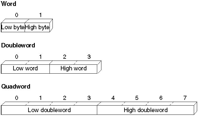
Figure 4.7 Integer Formats
Although the TYPEDEF directive’s primary purpose is to define pointer variables (see "Defining Pointer Types with TYPEDEF" in Chapter 3), you can also use TYPEDEF to create an alias for any integer type. For example, these declarations
char TYPEDEF
SBYTE
long TYPEDEF DWORD
float TYPEDEF REAL4
double TYPEDEF REAL8
allow you to use char, long, float, or double in your programs if you prefer the C data labels.
Data Initialization
You can initialize variables when you declare them with constants or expressions that evaluate to constants. The assembler generates an error if you specify an initial value too large for the variable type.
A ? in place of an initializer indicates you do not require the assembler to initialize the variable. The assembler allocates the space but does not write in it. Use ? for buffer areas or variables your program will initialize at run time.
You can declare and initialize variables in one step with the data directives, as these examples show.
integer BYTE 16
; Initialize byte to 16
negint SBYTE -16 ; Initialize signed byte to -16
expression WORD 4*3 ; Initialize word to 12
signedexp SWORD 4*3 ; Initialize signed word to 12
empty QWORD ? ; Allocate uninitialized long int
BYTE 1,2,3,4,5,6 ; Initialize six unnamed bytes
long DWORD 4294967295 ; Initialize doubleword to
; 4,294,967,295
longnum SDWORD -2147433648 ; Initialize signed doubleword
; to -2,147,433,648
tb TBYTE 2345t ; Initialize 10-byte binary number
For information on arrays and on using the DUP operator to allocate initializer lists, see "Arrays and Strings" in Chapter 5.
Working with Simple Variables
Once you have declared integer variables in your program, you can use them to copy, move, and sign-extend integer variables in your MASM code. This section shows how to do these operations as well as how to add, subtract, multiply, and divide numbers and do bit-level manipulations with logical, shift, and rotate instructions.
Since MASM instructions require operands to be the same size, you may need to operate on data in a size other than that originally declared. You can do this with the PTR operator. For example, you can use the PTR operator to access the high-order word of a DWORD-size variable. The syntax for the PTR operator is
type PTR expression
where the PTR operator forces expression to be treated as having the type specified. An example of this use is
.DATA
num DWORD 0
.CODE
mov ax, WORD
PTR num[0] ; Loads a word-size value from
mov dx, WORD PTR num[2] ; a doubleword variable
Copying Data
The primary instructions for moving data from operand to operand and loading them into registers are MOV (Move), XCHG (Exchange), CWD (Convert Word to Double), and CBW (Convert Byte to Word).
Moving Data
The most common method of moving data, the MOV instruction, is essentially a copy instruction, since it always copies the source operand to the destination operand without affecting the source. After a MOV instruction, the source and destination operands contain the same value.
The following example illustrates the MOV instruction. As explained in "General-Purpose Registers," Chapter 1, you cannot move a value from one location in memory to another in a single operation.
; Immediate
value moves
mov ax, 7 ; Immediate to register
mov mem, 7 ; Immediate to memory direct
mov mem[bx], 7 ; Immediate to memory indirect
; Register moves
mov mem, ax ; Register to memory direct
mov mem[bx], ax ; Register to memory indirect
mov ax, bx ; Register to register
mov ds, ax ; General register to segment register
; Direct memory moves
mov ax, mem ; Memory direct to register
mov ds, mem ; Memory to segment register
; Indirect memory moves
mov ax, mem[bx] ; Memory indirect to register
mov ds, mem[bx] ; Memory indirect to segment register
; Segment register moves
mov mem, ds ; Segment register to memory
mov mem[bx], ds ; Segment register to memory indirect
mov ax, ds ; Segment register to general register
The following example shows several common types of moves that require two instructions.
; Move
immediate to segment register
mov ax, DGROUP ; Load AX with immediate value
mov ds, ax ; Copy AX to segment register
; Move memory to memory
mov ax, mem1 ; Load AX with memory value
mov mem2, ax ; Copy AX to other memory
; Move segment register to segment register
mov ax, ds ; Load AX with segment register
mov es, ax ; Copy AX to segment register
The MOVSX and MOVZX instructions for the 80386/486 processors extend and copy values in one step. See "Extending Signed and Unsigned Integers," following.
Exchanging Integers
The XCHG (Exchange) instruction exchanges the data in the source and destination operands. You can exchange data between registers or between registers and memory, but not from memory to memory:
xchg ax, bx ;
Put AX in BX and BX in AX
xchg memory, ax ; Put "memory" in AX and AX in "memory"
; xchg mem1, mem2 ; Illegal- can't exchange memory
locations
Extending Signed and Unsigned Integers
Since moving data between registers of different sizes is illegal, you must "sign-extend" integers to convert signed data to a larger size. Sign-extending means copying the sign bit of the unextended operand to all bits of the operand’s next larger size. This widens the operand while maintaining its sign and value.
8086-based processors provide four instructions specifically for sign-extending. The four instructions act only on the accumulator register (AL, AX, or EAX), as shown in the following list.
Instruction Sign-extend
CBW (convert byte to word) AL to AX
CWD (convert word to doubleword) AX to DX:AX
CWDE (convert word to doubleword extended)* AX to EAX
CDQ (convert doubleword to quadword)* EAX to EDX:EAX
*Requires an extended register and applies only to 80386/486 processors.
On the 80386/486 processors, the CWDE instruction converts a signed 16-bit value in AX to a signed 32-bit value in EAX. The CDQ instruction converts a signed 32-bit value in EAX to a signed 64-bit value in the EDX:EAX register pair.
This example converts signed integers using CBW, CWD, CWDE, and CDQ.
.DATA
mem8 SBYTE -5
mem16 SWORD +5
mem32 SDWORD -5
.CODE
.
.
.
mov al, mem8 ; Load 8-bit -5 (FBh)
cbw ; Convert to 16-bit -5 (FFFBh) in AX
mov ax, mem16 ; Load 16-bit +5
cwd ; Convert to 32-bit +5 (0000:0005h) in DX:AX
mov ax, mem16 ; Load 16-bit +5
cwde ; Convert to 32-bit +5 (00000005h) in EAX
mov eax, mem32 ; Load 32-bit -5 (FFFFFFFBh)
cdq ; Convert to 64-bit -5
; (FFFFFFFF:FFFFFFFBh) in EDX:EAX
These four instructions efficiently convert unsigned values as well, provided the sign bit is zero. This example, for instance, correctly widens mem16 whether you treat the variable as signed or unsigned.
The processor does not differentiate between signed and unsigned values. For instance, the value of mem8 in the previous example is literally 251 (0FBh) to the processor. It ignores the human convention of treating the highest bit as an indicator of sign. The processor can ignore the distinction between signed and unsigned numbers because binary arithmetic works the same in either case.
If you add 7 to mem8, for example, the result is 258 (102h), a value too large to fit into a single byte. The byte-sized mem8 can accommodate only the least-significant digits of the result (02h), and so receives the value of 2. The result is the same whether we treat mem8 as a signed value (-5) or unsigned value (251).
This overview illustrates how the programmer, not the processor, must keep track of which values are signed or unsigned, and treat them accordingly. If AL=127 (01111111y), the instruction CBW sets AX=127 because the sign bit is zero. If AL=128 (10000000y), however, the sign bit is 1. CBW thus sets AX=65,280
(FF00h), which may not be what you had in mind if you assumed AL originally held an unsigned value.To widen unsigned values, explicitly set the higher register to zero, as shown in the following example:
.DATA
mem8 BYTE 251
mem16 WORD 251
.CODE
.
.
.
mov al, mem8 ; Load 251 (FBh) from 8-bit memory
sub ah, ah ; Zero upper half (AH)
mov ax, mem16 ; Load 251 (FBh) from 16-bit memory
sub dx, dx ; Zero upper half (DX)
sub eax, eax ; Zero entire extended register (EAX)
mov ax, mem16 ; Load 251 (FBh) from 16-bit memory
The 80386/486 processors provide instructions
that move and extend a value to a larger data size in a single
step. MOVSX moves a signed value into a register and
sign-extends it. MOVZX moves an unsigned value into a
register and zero-
extends it.
; 80386/486
instructions
movzx dx, bl ; Load unsigned 8-bit value into
; 16-bit register and zero-extend
These special 80386/486 instructions usually execute much faster than the equivalent 8086/286 instructions.
Adding and Subtracting Integers
You can use the ADD, ADC, INC, SUB, SBB, and DEC instructions for adding, incrementing, subtracting, and decrementing values in single registers. You can also combine them to handle larger values that require two registers for storage.
Adding and Subtracting Integers Directly
The ADD, INC (Increment), SUB, and DEC (Decrement) instructions operate on 8- and 16-bit values on the 8086-80286 processors, and on 8-, 16-, and 32-bit values on the 80386/486 processors. They can be combined with the ADC and SBB instructions to work on 32-bit values on the 8086 and 64-bit values on the 80386/486 processors. (See "Adding and Subtracting in Multiple Registers," following.)
These instructions have two requirements:
1. If there are two operands, only one operand can be a memory operand.
2. If there are two operands, both must be the same size.
To meet the second requirement, you can use the PTR operator to force an operand to the size required. (See "Working with Simple Variables," previous.) For example, if Buffer is an array of bytes and BX points to an element of the array, you can add a word from Buffer with
add ax, WORD
PTR Buffer[bx] ; Add word from byte array
The next example shows 8-bit signed and unsigned addition and subtraction.
.DATA
mem8 BYTE 39
.CODE
; Addition
; signed unsigned
mov al, 26 ; Start with register 26 26
inc al ; Increment 1 1
add al, 76 ; Add immediate 76 + 76
; ---- ----
; 103 103
add al, mem8 ; Add memory 39 + 39
; ---- ----
mov ah, al ; Copy to AH -114 142
+overflow
add al, ah ; Add register 142
; ----
; 28+carry
; Subtraction
; signed unsigned
mov al, 95 ; Load register 95 95
dec al ; Decrement -1 -1
sub al, 23 ; Subtract immediate -23 -23
; ---- ----
; 71 71
sub al, mem8 ; Subtract memory -122 -122
; ---- ----
; -51 205+sign
mov ah, 119 ; Load register 119
sub al, ah ; and subtract -51
; ----
; 86+overflow
The INC and DEC instructions treat integers as unsigned values and do not update the carry flag for signed carries and borrows.
When the sum of 8-bit signed operands exceeds 127, the processor sets the overflow flag. (The overflow flag is also set if both operands are negative and the sum is less than or equal to -128.) Placing a JO (Jump on Overflow) or INTO (Interrupt on Overflow) instruction in your program at this point can transfer control to error-recovery statements. When the sum exceeds 255, the processor sets the carry flag. A JC (Jump on Carry) instruction at this point can transfer control to error-recovery statements.
In the previous subtraction example, the processor sets the sign flag if the result goes below 0. At this point, you can use a JS (Jump on Sign) instruction to transfer control to error-recovery statements. Jump instructions are described in the "Jumps" section in Chapter 7.
Adding and Subtracting in Multiple Registers
You can add and subtract numbers larger than the register size on your processor with the ADC (Add with Carry) and SBB (Subtract with Borrow) instructions. If the operations prior to an ADC or SBB instruction do not set the carry flag, these instructions are identical to ADD and SUB. When you operate on large values in more than one register, use ADD and SUB for the least significant part of the number and ADC or SBB for the most significant part.
The following example illustrates multiple-register addition and subtraction. You can also use this technique with 64-bit operands on the 80386/486 processors.
.DATA
mem32 DWORD 316423
mem32a DWORD 316423
mem32b DWORD 156739
.CODE
.
.
.
; Addition
mov ax, 43981 ; Load immediate 43981
sub dx, dx ; into DX:AX
add ax, WORD PTR mem32[0] ; Add to both + 316423
adc dx, WORD PTR mem32[2] ; memory words ------
; Result in DX:AX 360404
; Subtraction
mov ax, WORD PTR mem32a[0] ; Load mem32 316423
mov dx, WORD PTR mem32a[2] ; into DX:AX
sub ax, WORD PTR mem32b[0] ; Subtract low - 156739
sbb dx, WORD PTR mem32b[2] ; then high ------
; Result in DX:AX 159684
For 32-bit registers on the 80386/486 processors, only two steps are necessary. If your program needs to be assembled for more than one processor, you can assemble the statements conditionally, as shown in this example:
.DATA
mem32 DWORD 316423
mem32a DWORD 316423
mem32b DWORD 156739
p386 TEXTEQU (@Cpu AND 08h)
.CODE
.
.
.
; Addition
IF p386
mov eax, 43981 ; Load immediate
add eax, mem32 ; Result in EAX
ELSE
.
. ; do steps in previous example
.
ENDIF
; Subtraction
IF p386
mov eax, mem32a ; Load memory
sub eax, mem32b ; Result in EAX
ELSE
.
. ; do steps in previous example
.
ENDIF
Since the status of the carry flag affects the results of calculations with ADC and SBB, be sure to turn off the carry flag with the CLC (Clear Carry Flag) instruction or use ADD or SUB for the first calculation, when appropriate.
Multiplying and Dividing Integers
The 8086 family of processors uses different multiplication and division instructions for signed and unsigned integers. Multiplication and division instructions also have special requirements depending on the size of the operands and the processor the code runs on.
Using Multiplication Instructions
The MUL instruction multiplies unsigned numbers. IMUL multiplies signed numbers. For both instructions, one factor must be in the accumulator register (AL for 8-bit numbers, AX for 16-bit numbers, EAX for 32-bit numbers). The other factor can be in any single register or memory operand. The result overwrites the contents of the accumulator register.
Multiplying two 8-bit numbers produces a 16-bit result returned in AX. Multiplying two 16-bit operands yields a 32-bit result in DX:AX. The 80386/486 processor handles 64-bit products in the same way in the EDX:EAX pair.
This example illustrates multiplication of signed 16- and 32-bit integers.
.DATA
mem16 SWORD -30000
.CODE
.
.
.
; 8-bit unsigned multiply
mov al, 23 ; Load AL 23
mov bl, 24 ; Load BL * 24
mul bl ; Multiply BL -----
; Product in AX 552
; overflow and carry set
; 16-bit signed multiply
mov ax, 50 ; Load AX 50
; -30000
imul mem16 ; Multiply memory -----
; Product in DX:AX -1500000
; overflow and carry set
A nonzero number in the upper half of the result (AH for byte, DX or EDX for word) sets the overflow and carry flags.
On the 80186-80486 processors, the IMUL instruction supports three additional operand combinations. The first syntax option allows for 16-bit multipliers producing a 16-bit product or 32-bit multipliers for 32-bit products on the 80386/486. The result overwrites the destination. The syntax for this operation is:
IMUL register16, immediate
The second syntax option specifies three operands for IMUL. The first operand must be a 16-bit register operand, the second a 16-bit memory (or register) operand, and the third a 16-bit immediate operand. IMUL multiplies the memory (or register) and immediate operands and stores the product in the register operand with this syntax:
IMUL register16,{ memory16 | register16}, immediate
For the 80386/486 only, a third option for IMUL allows an additional operand for multiplication of a register value by a register or memory value. The syntax is:
IMUL register,{register | memory}
The destination can be any 16-bit or 32-bit register. The source must be the same size as the destination.
In all of these options, products too large to fit in 16 or 32 bits set the overflow and carry flags. The following examples show these three options for IMUL.
imul dx, 456 ;
Multiply DX times 456 on 80186-80486
imul ax, [bx],6 ; Multiply the value pointed to by BX
; by 6 and put the result in AX
imul dx, ax ; Multiply DX times AX on 80386
imul ax, [bx] ; Multiply AX by the value pointed to
; by BX on 80386
The IMUL instruction with multiple operands can be used for either signed or unsigned multiplication, since the 16-bit product is the same in either case. To get a 32-bit result, you must use the single-operand version of MUL or IMUL.
Using Division Instructions
The DIV instruction divides unsigned numbers, and IDIV divides signed numbers. Both return a quotient and a remainder.
Table 4.1 summarizes the division operations. The dividend is the number to be divided, and the divisor is the number to divide by. The quotient is the result. The divisor can be in any register or memory location except the registers where the quotient and remainder are returned.
Table 4.1 Division Operations
Size of Operand Dividend Register Size of Divisor Quotient Remainder
16 bits AX 8 bits AL AH
32 bits DX:AX 16 bits AX DX
64 bits (80386 and 80486) EDX:EAX 32 bits EAX EDX
Unsigned division does not require careful attention to flags. The following examples illustrate signed division, which can be more complex.
.DATA
mem16 SWORD -2000
mem32 SDWORD 500000
.CODE
.
.
.
; Divide 16-bit unsigned by 8-bit
mov ax, 700 ; Load dividend 700
mov bl, 36 ; Load divisor DIV 36
div bl ; Divide BL ------
; Quotient in AL 19
; Remainder in AH 16
; Divide 32-bit signed by 16-bit
mov ax, WORD PTR mem32[0] ; Load into DX:AX
mov dx, WORD PTR mem32[2] ; 500000
idiv mem16 ; DIV -2000
; Divide memory ------
; Quotient in AX -250
; Remainder in DX 0
; Divide 16-bit signed by 16-bit
mov ax, WORD PTR mem16 ; Load into AX -2000
cwd ; Extend to DX:AX
mov bx,-421 ; DIV -421
idiv bx ; Divide by BX -----
; Quotient in AX 4
; Remainder in DX -316
If the dividend and divisor are the same size, sign-extend or zero-extend the dividend so that it is the length expected by the division instruction. See "Extending Signed and Unsigned Integers," earlier in this chapter.
Manipulating Numbers at the Bit Level
The instructions introduced so far in this chapter access numbers at the byte or word level. The logical, shift, and rotate instructions described in this section access individual bits in a number. You can use logical instructions to evaluate characters and do other text and screen operations. The shift and rotate instructions do similar tasks by shifting and rotating bits through registers. This section reviews some applications of these bit-level operations.
Logical Instructions
The logical instructions AND, OR, and XOR compare bits in two operands. Based on the results of the comparisons, the instructions alter bits in the first (destination) operand. The logical instruction NOT also changes bits, but operates on a single operand.
The following list summarizes these four logical instructions. The list makes reference to the "destination bit," meaning the bit in the destination operand. The terms "both bits" and "either bit" refer to the corresponding bits in the source and destination operands. These instructions include:
Instruction Sets Destination Bit If Clears Destination Bit If
AND Both bits set Either or both bits clear
OR Either or both bits set Both bits clear
XOR Either bit (but not both) set Both bits set or both clear
NOT Destination bit clear Destination bit set
Note
Do not confuse logical instructions with the logical operators, which perform these operations at assembly time, not run time. Although the names are the same, the assembler recognizes the difference.
The following example shows the result of the AND, OR, XOR, and NOT instructions operating on a value in the AX register and in a mask. A mask is any number with a pattern of bits set for an intended operation.
mov ax, 035h ;
Load value 00110101
and ax, 0FBh ; Clear bit 2 AND 11111011
; --------
; Value is now 31h 00110001
or ax, 016h ; Set bits 4,2,1 OR 00010110
; --------
; Value is now 37h 00110111
xor ax, 0ADh ; Toggle bits 7,5,3,2,0 XOR 10101101
; --------
; Value is now 9Ah 10011010
not ax ; Value is now 65h 01100101
The AND instruction clears unmasked bits - that is, bits not protected by 1 in the mask. To mask off certain bits in an operand and clear the others, use an appropriate masking value in the source operand. The bits of the mask should be 0 for any bit positions you want to clear and 1 for any bit positions you want to remain unchanged.
The OR instruction forces specific bits to 1 regardless of their current settings. The bits of the mask should be 1 for any bit positions you want to set and 0 for any bit positions you want to remain unchanged.
The XOR instruction toggles the value of specific bits on and off - that is, reverses them from their current settings. This instruction sets a bit to 1 if the corresponding bits are different or to 0 if they are the same. The bits of the mask should be 1 for any bit positions you want to toggle and 0 for any bit positions you want to remain unchanged.
The following examples show an application for each of these instructions. The code illustrating the AND instruction converts a "y" or "n" read from the keyboard to uppercase, since bit 5 is always clear in uppercase letters. In the example for OR, the first statement is faster and uses fewer bytes than cmp bx, 0. When the operands for XOR are identical, each bit cancels itself, producing 0.
;AND example -
converts characters to uppercase
mov ah, 7 ; Get character without echo
int 21h
and al, 11011111y ; Convert to uppercase by clearing bit 5
cmp al, 'Y' ; Is it Y?
je yes ; If so, do Yes actions
. ; Else do No actions
.
yes: .
;OR example - compares operand to 0
or bx, bx ; Compare to 0
jg positive ; BX is positive
jl negative ; BX is negative
; else BX is zero
;XOR example - sets a register to 0
xor cx, cx ; 2 bytes, 3 clocks on 8088
sub cx, cx ; 2 bytes, 3 clocks on 8088
mov cx, 0 ; 3 bytes, 4 clocks on 8088
On the 80386/486 processors, the BSF (Bit Scan Forward) and the BSR (Bit Scan Reverse) instructions perform operations like those of the logical instructions. They scan the contents of a register to find the first-set or last-set bit. You can use BSF or BSR to find the position of a set bit in a mask or to check if a register value is 0.
Shifting and Rotating Bits
The 8086-based processors provide a complete set of instructions for shifting and rotating bits. Shift instructions move bits a specified number of places to the right or left. The last bit in the direction of the shift goes into the carry flag, and the first bit is filled with 0 or with the previous value of the first bit.
Rotate instructions also move bits a specified number of places to the right or left. For each bit rotated, the last bit in the direction of the rotate operation moves into the first bit position at the other end of the operand. With some variations, the carry bit is used as an additional bit of the operand. Figure 4.2 illustrates the eight variations of shift and rotate instructions for 8-bit operands. Notice that SHL and SAL are identical.
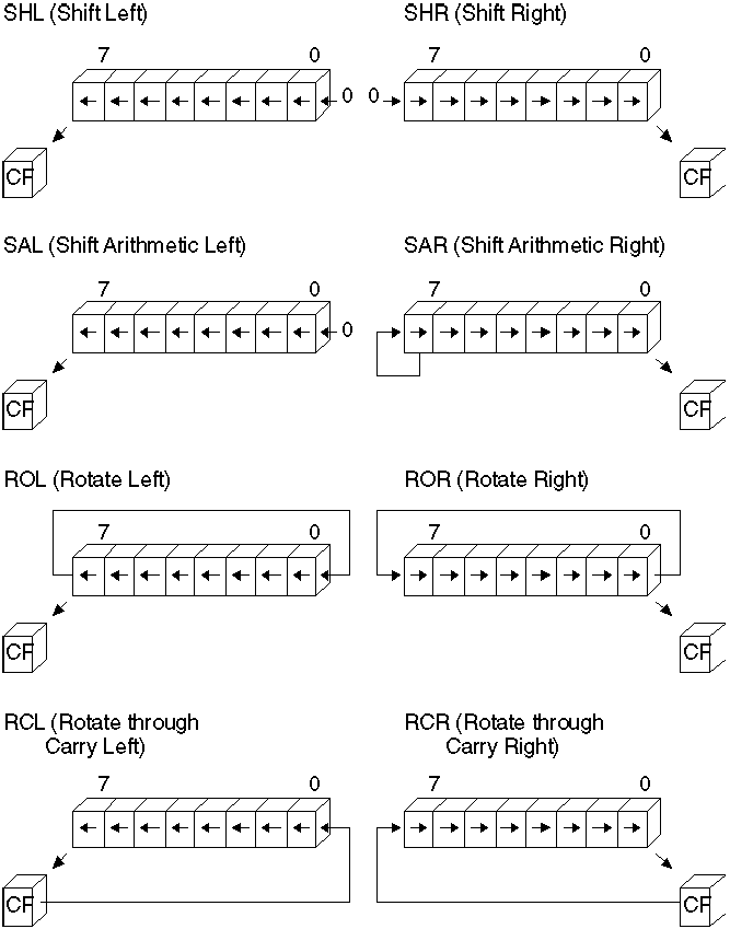
Figure 4.8 Shifts and Rotates
All shift instructions use the same format. Before the instruction executes, the destination operand contains the value to be shifted; after the instruction executes, it contains the shifted operand. The source operand contains the number of bits to shift or rotate. It can be the immediate value 1 or the CL register. The 8088 and 8086 processors do not accept any other values or registers with these instructions.
Starting with the 80186 processor, you can use 8-bit immediate values larger than 1 as the source operand for shift or rotate instructions, as shown here:
shr bx, 4 ; 9
clocks, 3 bytes on 80286
The following statements are equivalent if the program must run on the 8088 or 8086 processor:
mov cl, 4 ; 2
clocks, 3 bytes on 80286
shr bx, cl ; 9 clocks, 2 bytes on 80286
; 11 clocks, 5 bytes total
Masks for logical instructions can be shifted to new bit positions. For example, an operand that masks off a bit or group of bits can be shifted to move the mask to a different position, allowing you to mask off a different bit each time the mask is used. This technique, illustrated in the following example, is useful only if the mask value is unknown until run time.
.DATA
masker BYTE 00000010y ; Mask that may change at run time
.CODE
.
.
.
mov cl, 2 ; Rotate two at a time
mov bl, 57h ; Load value to be changed 01010111y
rol masker, cl ; Rotate two to left 00001000y
or bl, masker ; Turn on masked values ---------
; New value is 05Fh 01011111y
rol masker, cl ; Rotate two more 00100000y
or bl, masker ; Turn on masked values ---------
; New value is 07Fh 01111111y
Multiplying and Dividing with Shift Instructions
You can use the shift and rotate instructions (SHR, SHL, SAR, and SAL) for multiplication and division. Shifting a value right by one bit has the effect of dividing by two; shifting left by 1 bit has the effect of multiplying by two. You can take advantage of shifts to do fast multiplication and division by powers of two. For example, shifting left twice multiplies by four, shifting left three times multiplies by eight, and so on.
Use SHR (Shift Right) to divide unsigned numbers. You can use SAR (Shift Arithmetic Right) to divide signed numbers, but SAR rounds negative numbers down - IDIV always rounds negative numbers up (toward 0). Division using SAR must adjust for this difference. Multiplication by shifting is the same for signed and unsigned numbers, so you can use either SAL or SHL.
Multiply and divide instructions are relatively slow, particularly on the 8088 and 8086 processors. When multiplying or dividing by a power of two, use shifts to speed operations by a factor of 10 or more. For example, these statements take only four clocks on an 8088 or 8086 processor:
sub ah, ah ;
Clear AH
shl ax, 1 ; Multiply byte in AL by 2
The following statements produce the same results, but take between 74 and 81 clocks on the 8088 or 8086 processors. The same statements take 15 clocks on the 80286 and between 11 and 16 clocks on the 80386. (For a discussion about instruction timings, see "A Word on Instruction Timings" in the Introduction.)
mov bl, 2 ;
Multiply byte in AL by 2
mul bl
As the following macro shows, it’s possible to multiply by any number - in this case, 10 - without resorting to the MUL instruction. However, such a procedure is no more than an interesting arithmetic exercise, since the additional code almost certainly takes more time to execute than a single MUL. You should consider using shifts in your program only when multiplying or dividing by a power of two.
mul_10 MACRO
factor ; Factor must be unsigned
mov ax, factor ; Load into AX
shl ax, 1 ; AX = factor * 2
mov bx, ax ; Save copy in BX
shl ax, 1 ; AX = factor * 4
shl ax, 1 ; AX = factor * 8
add ax, bx ; AX = (factor * 8) + (factor * 2)
ENDM ; AX = factor * 10
Here’s another macro that divides by 512. In contrast to the previous example, this macro uses little code and operates faster than an equivalent DIV instruction.
div_512 MACRO
dividend ; Dividend must be unsigned
mov ax, dividend ; Load into AX
shr ax, 1 ; AX = dividend / 2 (unsigned)
xchg al, ah ; XCHG is like rotate right 8
; AL = (dividend / 2) / 256
cbw ; Clear upper byte
ENDM ; AX = (dividend / 512)
If you need to shift a value that is too large to fit in one register, you can shift each part separately. The RCR (Register Carry Right) and RCL (Register Carry Left) instructions carry values from the first register to the second by passing the leftmost or rightmost bit through the carry flag.
This example shifts a multiword value.
.DATA
mem32 DWORD 500000
.CODE
; Divide 32-bit unsigned by 16
mov cx, 4 ; Shift right 4 500000
again: shr WORD PTR mem32[2], 1 ; Shift into carry DIV 16
rcr WORD PTR mem32[0], 1 ; Rotate carry in ------
loop again ; 31250
Since the carry flag is treated as part of the operand (it’s like using a 9-bit or 17-bit operand), the flag value before the operation is crucial. The carry flag can be adjusted by a previous instruction, but you can also set or clear the flag directly with the CLC (Clear Carry Flag), CMC (Complement Carry Flag), and STC (Set Carry Flag) instructions.
On the 80386 and 80486 processors, an alternate method for multiplying quickly by constants takes advantage of the LEA (Load Effective Address) instruction and the scaling of indirect memory operands. By using a 32-bit value as both the index and the base register in an indirect memory operand, you can multiply by the constants 2, 3, 4, 5, 8, and 9 more quickly than you can by using the MUL instruction. LEA calculates the offset of the source operand and stores it into the destination register, EBX, as this example shows:
lea ebx,
[eax*2] ; EBX = 2 * EAX
lea ebx, [eax*2+eax] ; EBX = 3 * EAX
lea ebx, [eax*4] ; EBX = 4 * EAX
lea ebx, [eax*4+eax] ; EBX = 5 * EAX
lea ebx, [eax*8] ; EBX = 8 * EAX
lea ebx, [eax*8+eax] ; EBX = 9 * EAX
Scaling of 80386 indirect memory operands is reviewed in "Indirect Memory Operands with 32-Bit Registers" in Chapter 3. LEA is introduced in "Loading Addresses into Registers" in Chapter 3.
The next chapter deals with more complex data types - arrays, strings, structures, unions, and records. Many of the operations presented in this chapter can also be applied to the data structures covered in Chapter 5, "Defining and Using Complex Data Types."
Questions:
| file: /Techref/language/masm/masmc04.htm, 61KB, , updated: 2018/10/4 18:56, local time: 2025/10/23 11:44,
216.73.216.20,10-1-5-169:LOG IN
|
| ©2025 These pages are served without commercial sponsorship. (No popup ads, etc...).Bandwidth abuse increases hosting cost forcing sponsorship or shutdown. This server aggressively defends against automated copying for any reason including offline viewing, duplication, etc... Please respect this requirement and DO NOT RIP THIS SITE. Questions? <A HREF="http://massmind.ecomorder.com/techref/language/masm/masmc04.htm"> CHAPTER 4</A> |
| Did you find what you needed? |
Welcome to ecomorder.com! |
|
The Backwoods Guide to Computer Lingo |
.