BYTE February 1978 page 169
At first glance, using a computer to build an analog filter seems like the height of overkill. Imagine an analog to digital converter, a microprocessor with memory and peripheral interfaces, a digital to analog converter, and more, just to do the job of a capacitor, a resistor and a coil of wire! People have been building analog filters for years without computers. How can an analog filter be constructed with a digital device like a microcomputer? Digital filtering may be the answer.
All right, you say, we must have some analog to digital conversion stage in there. True enough. A digital filter uses periodic samples of an analog waveform as input. These samples are digitally manipulated in a computer of some sort and then converted back to analog form by a digital to analog converter. One input sample is converted to one output voltage. By integrating this output sequence, the digital process appears to have a continuous analog output.
The rest of this article describes the manipulations we must perform on the digital samples in order to simulate the performance of simple filters. The mathematics is quite complex and is available in many texts. We will try to concentrate here on the practical implementation of such a filter.
|
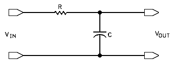
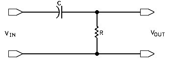
Figure 1: Simple resistor-capacitor (RC) low pass filter. |
Let us take for example the Simple RC (resistor-capacitor) low pass filter shown in figure 1. This circuit passes frequencies in the input voltage that are lower than some critical frequency (called the cutoff frequency) determined by the resistor and capacitor values, while severely attenuating any higher frequencies.
The output voltage Vout, then, is simply a selectively reduced version of Vin (input voltage). The resistor drops the output voltage, as does the voltage that goes into charging C. At first, Vout = a * Vin (where the constant a is the amount of attenuation caused by R and C). It can be shown that a=1/RC (where R is in ohms and C is in farads).
The voltage change with time across a capacitor is an exponential function. If the voltage at time zero is V, then the voltage at time t is given by Ve^(-at) (a is the Same constant as above).
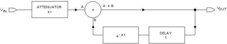
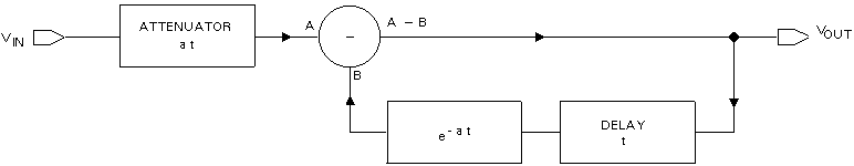
Now, let us consider that the input is a series of samples, where samples occur every t seconds. The output voltage at any given time is just the algebraic sum of the attenuated input voltage and the voltage on the capacitor at that time. In other words: t=0 output=aV t=1 output=av +aV e^(-at) t=2 output=aV +aV e^(-at) + aV e^(-2at) After a number of samples, the output voltage becomes the sum of a number of such terms. Since the terms are similar, and e^(-nat) = [e^(-at)]^n we need to compute the exponential term only once, and multiply it by itself repeatedly to get the extra terms of the series. Figure 2 shows the equivalent circa it of the RC low pass filter in figure 1, shown in block diagram form. It consists of an attenuator (factor a), an exponential and time delay (the capacitor), and a summer.
Figure 2: Filtering process performed by the circuit of figure I in block form. |
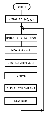
Figure 3: Flowchart for |
We then jump to figure 3, which shows a flowchart of this process. The only change is that the attenuation factor is given as at, where t is the period between samples. Much of the input to the filter is lost because its frequency is outside the filter range. This does not change the shape of the output (the important factor), but only the magnitude of the output (like adding gain to the filter). If you have accepted that last bit of sleight of hand, you can see that figure 3 is a block diagram of a program to perform low pass filtering.
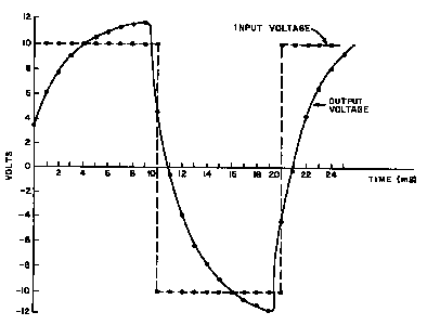
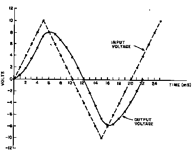
Figure 4: Result of passing a 50 Hz square wave through the digital low pass filter program. |
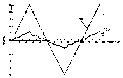
Figure 4 shows the output of such a digital filter program when the input is a square wave with maximum and minimum values of +10V and -10V, respectively, and a frequency of 50 Hz. The sampling rate is 20 samples per cycle, thus t=1 ms. The RC constant a is arbitrarily set equal to 360.
Figure 5: Result of passing a 50 Hz triangular wave through the low pass digital filter program. |
The removal of the high frequency components of the square wave is evident. Figure 5 shows the filter response to a triangular wave at the same frequency. The output is nearly all at the fundamental frequency of the input, as one would expect of a low pass filter.
Figure 6: Simple resistor- capacitor (RC) high pass filter. |
Now, how do we simulate high pass filters like the one in figure 6? Here the output voltage is the difference of the attenuated input and the capacitor voltage (since the capacitor resists rapid changes in its charge).
Thus, figure 7 is a simulation of a high pass filter. It is identical to the low pass filter except that A+B becomes A-B.
Figure 7: Filtering process performed by the circuit of figure 6 in block form. By changing a sum to a difference we convert the block diagram from a low to a high pass filter. |
Figure 8: Result of passing the 50 Hz square wave used in figure 4 through a high pass digital filter program.
Figure 9: Result of passing the 50 Hz triangular wave used in figure 5 through a high pass digital filter. |
Figures 8 and 9 show the response of a high pass filter program to the same inputs as those in figures 4 and 5. The constants are the same, but the change in output is striking.
One of the main features of software instead of hardware implementation is the ease with which software can be modified.
A low pass filter changes to a high pass filter by changing an add to a subtract! Filter constants can be easily modified, amplification added, etc. More complicated filters, such as band pass types, can be simulated by combining appropriate high and low pass feedback loops with adders and subtracters.
The filters can be dynamic, adapting to the input. They can be programmed. This would seem to suggest uses in computer generated music systems, audio processing, removing noise from signals, etc. If one has to convert analog signals to digital form at some point in a design, then it may be useful to do much of the filtering at the digital level, How can you perform digital filtering in real time without an exponential routine in your computer? The answer is that the exponential function is a constant. It can be programmed in, or provided by a table. The critical points are the two multiplications: one by at and the other by e^(-at). Both of these values are usually less than 1 for a real filter. (In the examples, at=.360 and e^(-at)=0.697.) What we can use is a routine called a fractional multiply. This is a routine that multiplies two values, one treated as an integer, and the other treated as a binary fraction.
One such routine, reproduced in listing 1, was written by Ira Chayut. For a detailed discussion of how it works see Programming Quickies, page 124, September 1976 BYTE.
;For 6800 (Original Code) FRACMUL STAA ARG1 ;ARG1:=A CLRA ;A1=0 MLOOP LSR ARG1 ;ARG1:=ARG1/2 ASLB ;CY:=MSB(B), B:=ASL(B,1) BCC NONADD ;IF CY=0 SKIP THE ADD ADDA ARG1 ;ELSE A:=A+ARG1 NONADD BNE MLOOP ;IF ARG2 NE 0 REITERATE RTS ;ELSE RETURN RESULT IN A ARG1 RMB 1 ;1 BYTE TEMP DATA AREA |
;For Ubicom / Parallax SX Microcontrollers fracmul ;This version depends on CARRYX being off. clr W ;W=0 :mloop clc rr arg1 ;ARG1:=ARG1/2 clc ; don't copy the carry rl arg2 ;CY:=MSB(ARG2), ; ARG2:=ASL(ARG2,1) snc ;IF CY=0 SKIP THE ADD add w,arg1 ;ELSE W:=W+ARG1 ; CARRYX must be off. test arg2 jnz @:mloop ;IF ARG2 NE 0 REITERATE ret ;ELSE RETURN RESULT IN W fracmul2 ;Version not sensitve to CARRRYX clr W ;W=0 :loop clc rr arg1 ;arg1 = arg1 / 2 clc snb arg2.7 ;if arg2 <= 128 add w,arg1 ; W = W + arg1 clc rl arg2 ;arg2 = arg2 * 2 test arg2 ;if arg2 <> 0 jnz @:loop ; goto loop ret ;return |
;For PIC Microcontrollers
fracmul
    CLRW            ;W=0
fracmul1
    BCF status,c
    RRF arg1        ;ARG1:=ARG1/2
    BCF status,c    ; don't copy the carry
    RLF arg2        ;CY:=MSB(ARG2),
                    ; ARG2:=ASL(ARG2,1)
    BTFSC status,c  ;IF CY=0 SKIP THE ADD
     ADDWF arg1,w   ;ELSE W:=W+ARG1
    MOVF arg2
    BTFSS status,z  ;IF ARG2 NE 0 REITERATE
    GOTO fracmul1
    RETLW 0h        ;ELSE RETURN RESULT IN W
|
| Listing 1: The fractional multiplication routine. The result is returned to the main program in the accumulator. | ||
This short subroutine forms the heart of a digital filter program for a microcontroller. In the program of listing 2 this subroutine is given the name FRACMUL. An analog to digital converter and sampler is assumed to provide 7 bit samples available at the location SAMPLE. The routine FILTER (see listing 2) is set up as part of an interrupt handler. A periodic interrupt is provided which initiates the sampling and causes a branch to the routine.
;For 6800 (Original Code)
    CLR BVAL       ;INITIALIZATION FILTER
    LDA A SAMPLE   ;A:= A/D SAMPLE (7-BITS)
    LDA B #92      ;B:= 'AT'
    JSR FRACMUL    ;MULTIPLY
    STA A TEMP     ;TEMP:= ANSWER
    LDA A BVAL     ;A:= BVAL
    LDA B #179     ;B:= E ^ (-AT) (LW BASE)
    JSR FRACMUL    ;MULTIPLY
    ADD A TEMP     ;SUM FOR LOW PASS FILTER
    STA A BVAL     ;RETURN ANSWER
    RTI

BVAL       RMB 1
TEMP       RMB 1
|
;For Ubicom / Parallax SX Microcontrollers
filter
	mov arg1,sample
at = 256* 360000/1000000
	mov arg2,#at
;for an RC filter with a
;360kOhm resistor and a
;1uF capacitor
	call fracmul2
	mov temp,w
	mov arg1,bval
	mov arg2,#179 ;e^(-at)
	call fracmul2
	add w,temp
	mov bval,w
	ret
|
| Listing 2: Low pass filter routine. This routine can be followed using the flowchart of figure 3 or the block diagram of figure 4. | |
FILTER assumes that the analog to digital converter is ready when it iS. It is also assumed that the location BVAL is zeroed initially. BVAL is the output of the filter.
The constants in the listing are those of the examples (92~=.360 * 256, and 179~=.697 * 256). FILTER should execute in about 200 to 300 cycles on each interrupt. Assuming a 1 ms sampling period, FILTER will consume about 33% of the time of a 1 MHz 6800 processor. On a 50Mhz SX, it takes about 4.18uS or about The memory occupied is negligible. FILTER is a practical program for use with audio frequencies. Listing 3 shows how easy it is to make FILTER either a high or low pass filter.
           SUB A TEMP     ;CHANGE TO HIGH PASS
           NEG A
Listing 3: To convert the low pass filter routine of listing 2 to a high pass filter routine, replace the ADD instruction with the above two lines. It can be seen that this is the only difference between the block diagrams of figures 2 and 7. |
Of course, more complex filters will be harder to design and will take more processing time. For really interesting filter applications, an external hardware multiplier will probably be needed, but such circuits are available reasonably, and they can be used for other applications in the computer system when not filtering.
Now, get in there and attack the math! It really isn't all that hard.
Copyright BYTE February 1978
| file: /Techref/new/letter/news0405.htm, 15KB, , updated: 2007/6/19 23:49, local time: 2025/10/15 18:31,
owner: JMN-EFP-786,
216.73.216.155,10-3-165-151:LOG IN
|
| ©2025 These pages are served without commercial sponsorship. (No popup ads, etc...).Bandwidth abuse increases hosting cost forcing sponsorship or shutdown. This server aggressively defends against automated copying for any reason including offline viewing, duplication, etc... Please respect this requirement and DO NOT RIP THIS SITE. Questions? <A HREF="http://massmind.ecomorder.com/techref/new/letter/news0405.htm"> A Simple Digital Filter</A> |
| Did you find what you needed? |
Welcome to ecomorder.com! |
Welcome to massmind.ecomorder.com! |
.